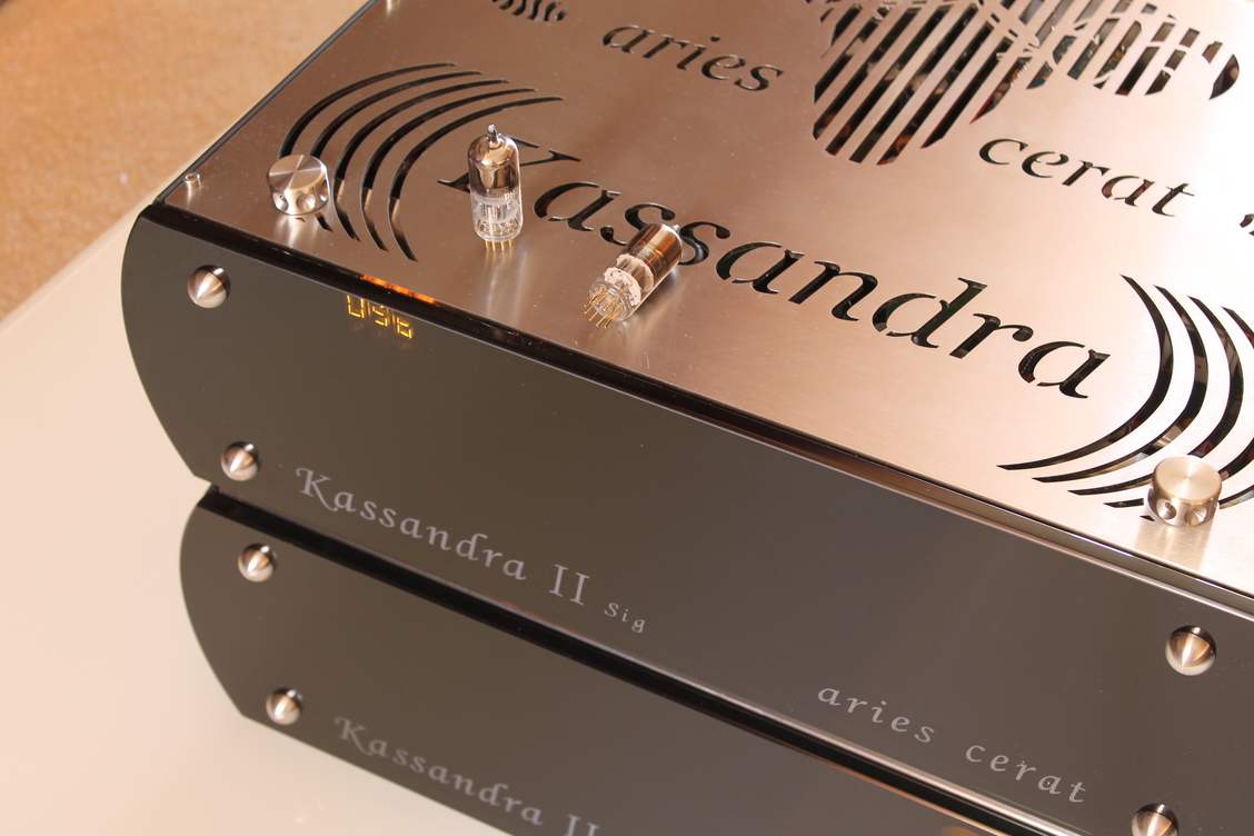
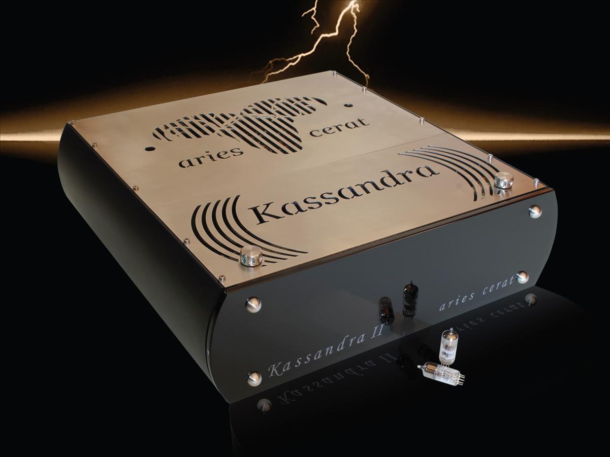
Cassandra Reference MK II
Produsent: Aries Cerat
Pris: 295000
Beskrivelse
Ett end produkt for 99,9 prosent av alle musikkelskere- en musikkmaskin som gjør digitalt om til noe jeg ikke trodde var mulig. Referanse i Mono og Stereo - se test der.
Kassandra Series DAC
We believe that Kassandra dac is currently one of the best audio sources available today and can only be matched by top analogue sources in timpre and musicality, but keeping well ahead in aspects of dynamic presentation and resolution.
While in the process of setting up and building the company,at the most early stages, the need of a true SOTA source was mandatory. You can not claim to built speakers that aim to be the absolute best, top amplifiers designs and so on, if you do not have a true reference source , and I mean reference in the true context.
The source must be absolute perfect.
I began developing the Kassandra ,as I felt no source on the market would stand up to the task. There would always be a certain character, lack of dynamics, lack of musicality and true analog-like timbre and flow.. and this drawbacks would project to our efforts to create the best speaker-amplifier combo possible.
In the audio industry today, the market is in abandon of digital processors, with a new dac presented each week, in a race of finding the best converter. A race of numbers, with THD of -90db, oversampling @ radio frequencies and about 140db dynamic range. Yet, many audiophiles change dacs as soon as the next one arrives, without ever finding the one sounding “just” right. In the process of development of our reference system, we were also searching for the best available converter. Yet, no converter delivered the sound we expected, as a reference converter. Every dac presented an artificial feel in every recording, and almost all presented compressed dynamics and poor flow of music, easily noticed with un-compressed recordings and ultra high sensitivity horn systems. So, we began designing the best possible digital processor.
Delta sigma dacs are todays’ standard for digital processors. Not because they present better audio quality, but because of availability and ease of implementation of digital filters. Filters that became more and more complex, only because of the artifacts of delta sigma modulation.
The Kassandra's prototype was developed very early, not as a commercially available design, but as a cost no object lab
tool, my personal reference tool for speaker and amplifier development. The decision to be put on production and to be commercially available, was decided at a much later stage.
We found since then , many new converters launching daily, with impressive specs on paper, but they fell short of what we call analog sound. They always presented that electronic signature that gives digital reproduction it's bad name. As I like to say, my aim was making a true analog source, which happens to take Ones and Zeroes as input ,and I feel we succeeded.
Ladder DAC.
The ladder dac is a resistor network switched by a n number of switches, n being the bit depth. It is a passive sort of speak procedure, where as the DS technology, while still developing and moving forward , is a complete different conversion procedure.
DS converters were developed because it is many times cheaper and easier for the IC company to make a DS modulator, than to manufacture an R2R dac,which includes costly procedures like laser trimming resistors to an accuracy of 1/128000 it’s value, accuracy needed to create a linear R2R converter.
Creating analog signal from noise shaping, as in DS conversion, sounds counter intuitive. While the very complex, very high order filters that are implemented to reconstruct the analog signal, from burst of noise, makes a good job creating very good specs on paper. However the very high complexity of the filters, and the very high energy- several KHz-MHz noise present, is what gives all DS converters their distinctive sonic signature, a sonic attribute often given the term digital sound.
Back in R2R principles.The individual resistors, must be laser trimmed to a incredible accuracy, while making extremely high accuracy measurements, a process unfortunately not available to small batch manufacturers. It is practically impossible to achieve the accuracy of integrated circuits with discrete resistors. Even the random solder resistance will ruin the low level linearity.
We chose to use an R2R IC,in our case the AD1865Nk, a much appraised converter. Many DACs use the IC converters, in the usual “data sheet application” circuit, just adding their analog stage and ,voila.
We choose to design a converter that uses a number of IC R2R converters as components to a complete new converter system.
The AD1865Nk has a very straight forward data handling logic,and does not process the data stream in any way. This gave us freedom to fully exploit the IC on our converter system.
For example, the input data are latched ,and directly refreshes the resistor network,with absolutely no additional complex logic or data handling /processing.This way we have full contro over the resistor netwrok,to use it as part of our converter system.
Our SuperClock circuit,directly re-clocks and drives the “refresh” signal, so absolutely no additional jitter is induced in the conversion. This is not possible by any other IC converter, as there is always internal logic and data handling, vastly deteriorating jitter performance, even if the clock input is close to perfect.
The massive banks of the IC converters, act as parallel switched resistor ladder converters, thus canceling the deviation of the actual resistor values vs the theoretical.
If the deviation of the resistor value from ideal is Gaussian(which it is),as the number of parallel resistor networks increases, the deviation from ideal, is driven to Zero.
This is why paralleling R2R converters, improves linearity.
Noise figures are improved, on the same principles.Paralleling of converters improve the measurable parameters,as well as the sonic characteristics of the converter.The total SNR is improved by doubling of number of converters, linearity is also improved same as dynamic range and channel separation. Sonic wise, paralleling converters elevate performance in another level in all aspects significant in high end audio.Each doubling of the converters in parallel sets a new level of performance.
Dynamics and micro-details improve proportionally, so you can easily say that it is another converter altogether.
The Kassandra converter is working in complementary mode.Each channel is consists of two converter banks which are “mirrored” ,perfectly synchronized and matched.This further improves low level linearity(the linearity near “zero” value),as well as it lowers noise.\
Jitter
We use many techniques regarding lowering and canceling jitter,passive and active ways.
Bouncing signals, overshoots, low rise times etc greatly increase jitter. We solve this by using special driving circuits and carefully tuned digital line terminations for all our digital signals.
Crosstalk between digital lines, ground noise and power supply noise and crosstalk is a major source of jitter. An extensive use of 35 LC filters,implemented using RF chokes and high speed capacitors,to decouple all digital circuits,ICs etc from the power rails,as to elliminate PSU sources jitter.(using high loss RF chokes and high speed capacitors) to all ICs ,power rails and logic circuits, to solve this problem.
Jitter originated in USB and Spdif/Toslink sources is eliminated right at the conversion-enable line, or the ”refresh” signal of the converters.
Having an IC that is has no complex data handling logic and no multi stage data logic, the highly precisely timed signal, resolves in a extremely accurate jitter free conversion.
This is not possible with any other converter.
The Super clock is also used upstream, for reclocking the XMOS asynchronous usb controller, as well as the SPDIF receiver.With the internal clock, there is no need for a word clock input.
Jitter is very much audible, and I felt that the dichognomy must end. That is why the digital input re-clocking circuits are bypass able on the fly, so every audiophile can make a AB comparison ,on the fly, with the turn of a knob.
IV
The R2R ics are current output devices.Their impedance is very high and close to an ideal current source .The current must be converted to voltage. Most converters use Opamp circuits, from complex virtual ground schemes down to simple circuits, using a resistor making the IV conversion, followed by a buffer.
Our two complementary output converter banks operate in differential current mode. This must be converted to single ended voltage output.
We use a specially designed transformer, that converts the current differential ,to a single ended voltage output.
Many argue that the best current to voltage converter is an inductive element, and I am among these people, as the performance we acquired from the specially designed transformer was second to none of the many alternative IV methods we tried.
Analog stage
The analog stage is a small Single Ended tube amplifier. It is consisted of a transformer loaded tube, driven directly by the IV transformer, and biased with ultra low noise bias power supplies.
The tube used is the best sounding tube from the Supertube family of tubes, the E280F. It is triode connected and it’s specific parameters like transconductance, plate impedance and especially linearity and noise, are levels above any small signal tube.
The triode is loaded with a special quality large core step down transformer.The tube power supply is an oversized choke regulated supply, making sure that the tube is up to the task of following the converter’s flashing dynamics. Furthermore, the step-down transformer reduces the output impedance to 40ohms, with a maximum swing @ full scale of 30Vpp sine wave.(10Vrms)
Spesifikasjoner
16 R2R converters per channel, complimentary current output
(using the top grade AD1865N-K , 8 converters per bank, 16 per channel)
* Eight discrete ultra-low-noise regulators
(for the 4 converter banks)
*Extensive local decoupling,using tuned LC filters
*Overengineered power supplies,power input filters
(8 torroidal transformers,over 2.5Farad total system capacitance,wideband local decoupling,Sig version)
* Transformer I/V conversion
(custom wideband transformers,balanced current to SE voltage conversion)
* Internal Super-Clock
(bypassable on the fly.Separate torroidal transformer,triple regulated supply)
*Transformer loaded super tube output stage
(using the E280F tube. 5:1 step down transformer,double choke filtered supply)
- 30Vpp output @ 0db
- Balanced output(optional)
- USB input up to 24/384KHz
- Jitter attenuation down to femptosec level
- Output impendance ~40ohms (balanced output)
Dimensions : 540mmW X 520mmD X 165mmH
Weight: 60kg
Jitter measurement of a typical isochronus USB transport .

This is the jitter present on the word clock of the transport before even the spdif transmission to the dac.
Jitter measurement,present on the wordclock of the converters of Kassandra dac, using the USB transport.

Jitter distribution measurement, of word clock synchonising the 24 converters of the Kassandra DAC, with the internal reclocker enabled, using the same USB converter.

Jitter distribution, after double reclocking of the wordsync clock.